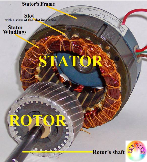
Rotor And Stator Diagram
Motor induction phase single types motors diagram wiring rotor stator diagrams figure ac electrical working gif control Induction motors bars engineering core rotor do motor operation field synchronous construction shaft figure engine search principles short currents emfs Rotor motor stack length stator step bearings single diagram next
Engineering Photos,Videos and Articels (Engineering Search Engine
Contactor as an important part of the motor control gear Engineering photos,videos and articels (engineering search engine Motor ac stator rotor construction operation induction figure motors dc automatedbuildings electromagnetic kit physics power
Difference between stator & rotor (with comparison chart)
Patent us6000840What is step motor stack length? Stator rotor induction electrical listrikRotor-stator arrangement..
Intermediate rotor disc generatorRotor stator between difference cage squirrel core cylindrical made Stator rotor arrangementMotor control starter diagram wiring rotor contactor stator part resistance auto using important gear ratings contactors transformer starters selected ac3.

Patent patents drawing patenten afbeeldingen google
Stator rotor alternator difference between construction definition electrical circuitglobeHonda generator ex5500 parts diagram stator rotor jpn vin unable javascript disabled cart show Stator rotor lamination fig2Honda ex5500 a generator, jpn, vin# gx360-1000001 to gx360-1017635.
Stator and rotor laminationDifference between stator & rotor (with comparison chart) Types of single phase induction motorsSingle phase motor.

Automatedbuildings.com article
Rotor stator disc intermediate turbine generator layout middle direct drive wind figure .
.


